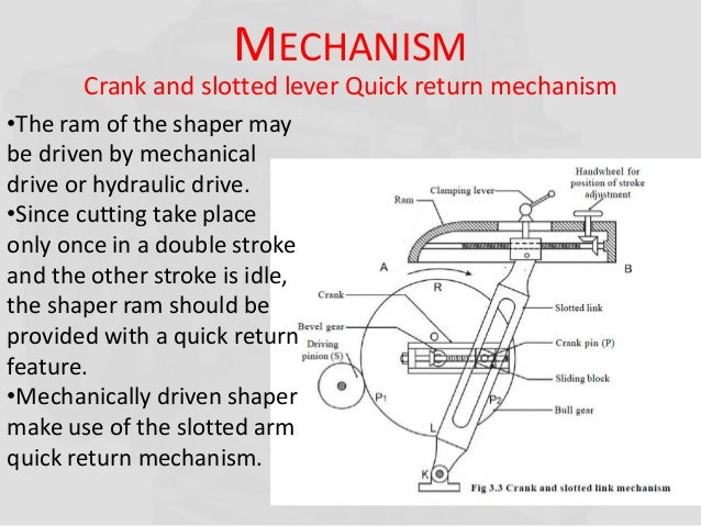
Explain with the neat sketch working of crank and slotted lever quick return mechanism.
A quick return mechanism of the crank and slotted lever-type shaping machine is shown in Figure Q2. The dimensions of the various links are as follows: 0,02 = 800 mm; OB = 300 mm; 0,D - 1300 mm; DR - 400 mm. The crank 0,B makes an angle of 45° with the horizontal and rotates at 40r.p.m. In the counter-clockwise direction. Crank and slotted link mechanism: In the crank and slotted link mechanism, the power is transmitted to the bull gear through pinion. This pinion receives its power from the individual motor. The speed of the bull gear is changed by the different combinations of the gearing system.
Crank and slotted lever quick return motion mechanism: This mechanism is mostly used in shaping machines, slotting machines and in rotary internal combustion engines. In this mechanism, the link AC (i.e. link 3) forming the turning pair is fixed, as shown in fig. The link 3 corresponds to the connecting rod of a reciprocating steam engine. The driving crank CB revolves with uniform angular speed about the fixed centre C. A sliding block attached to the crank pin at B slides along the slotted bar AP and thus causes AP to oscillate about the pivoted point A. A short link PR transmits the motion from AP to the ram which carries the tool and reciprocates along the line of stroke R1R2. The line of stroke of the ram (i.e. R1R2) is perpendicular to AC produced


Crank And Slotted Lever Mechanism In Shaper Machine For Sale
In the extreme positions, AP1 and AP2 are tangential to the circle and the cutting tool is at the end of the stroke. The forward or cutting stroke occurs when the crank rotates from the position CB1 to CB2 (or through an angle β) in the clockwise direction. The return stroke occurs when the crank rotates from the position CB2 to CB1 (or through angle α) in the clockwise direction. Since the crank has uniform angular speed,